Understanding the Studio Patchbay A Comprehensive Guide to Signal Routing Workflow Optimization and Hardware Integration

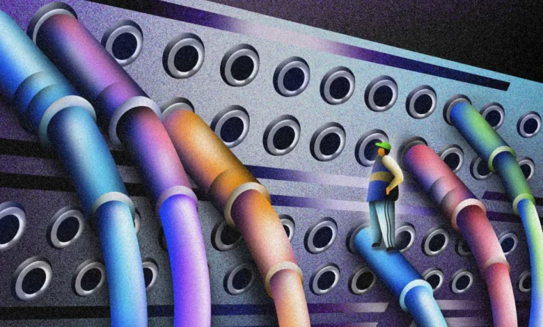
The modern recording environment, whether a sprawling commercial facility or a sophisticated home project studio, relies heavily on the efficiency of signal flow. Central to this efficiency is the patchbay, a hardware component that serves as the central nervous system for audio routing. By consolidating the inputs and outputs of all studio equipment—including microphones, synthesizers, outboard processors, and audio interfaces—into a single, accessible panel, the patchbay eliminates the need for manual cable swapping behind heavy equipment racks. This transition from a chaotic "spaghetti" of cables to a streamlined, logical interface represents a critical milestone in a producer’s or engineer’s technical evolution.
The Essential Function of a Patchbay in the Modern Studio
At its core, a patchbay is a passive bridge. It does not typically amplify or process sound; rather, it provides a centralized location where every connection point in a studio meets. In a purely digital workflow, such as one utilizing a Digital Audio Workstation (DAW) like Ableton Live, Logic Pro, or FL Studio, routing is handled via software algorithms. When a user inserts a software plugin, the DAW internally reroutes the digital signal through the processor. However, in a hybrid or analog environment, these connections must be physically established.
Without a patchbay, connecting a hardware synthesizer to an external compressor and then to an audio interface requires reaching behind each unit, unplugging existing cables, and threading new ones. This process is not only time-consuming but also places mechanical strain on the jacks of expensive hardware. The patchbay solves this by bringing every rear-panel connection to a front-facing interface, allowing for complex routing changes to be made in seconds using short "patch cables."
Historical Context and Evolution of Patching Systems
The technology of the patchbay finds its origins in the early telecommunications industry. In the late 19th and early 20th centuries, telephone operators used massive plug-boards to manually connect callers. This "switchboard" technology was eventually adopted by radio broadcast engineers and later by recording studios during the golden age of analog consoles.
In the mid-20th century, as studios began incorporating more outboard gear—such as the iconic Teletronix LA-2A or Pultec EQs—the need for a standardized routing system became apparent. The industry eventually settled on several formats, most notably the 1/4-inch TRS (Tip-Ring-Sleeve) patchbay for prosumer use and the TT (Tiny Telephone) or Bantam connector for professional large-format consoles. Today, while digital routing has become more prevalent, the resurgence of analog hardware has made the patchbay more relevant than ever for engineers seeking the "tactile" sound of hardware.
Technical Architecture: Understanding the Front and Rear Logic
A standard patchbay is typically housed in a 19-inch rack-mountable chassis and consists of two rows of jacks on both the front and the back. To utilize the system effectively, one must adhere to the industry-standard convention of signal flow:
- The Rear Panel (Permanent Connections): The back of the patchbay is where the "permanent" cabling resides. Following standard protocol, the top row of the rear panel is connected to the outputs of your equipment (e.g., the output of a synth, the output of a preamp, or the line outputs of an audio interface). The bottom row of the rear panel is connected to the inputs of your equipment (e.g., the inputs of a compressor, the inputs of an effect unit, or the line inputs of an audio interface).
- The Front Panel (Dynamic Routing): The front of the patchbay mirrors the back. The top row represents the outputs of your gear, and the bottom row represents the inputs. By connecting a patch cable from a top-row jack to a bottom-row jack on the front panel, you complete the circuit, sending the signal from a source to a destination.
This logical separation—outputs on top, inputs on bottom—is fundamental. It allows an engineer to visualize the signal as "falling" from the top row into the bottom row.
Signal Flow Configurations: Normaling Explained
The true power of a patchbay lies in its internal "normaling" configurations. These settings determine how the top and bottom jacks interact when no patch cable is inserted into the front panel. Understanding these configurations is vital for preventing feedback loops and optimizing workflow.
Full-Normal Configuration
In a full-normal setup, the top jack is internally wired to the bottom jack directly below it. This is ideal for "default" signal paths. For example, if your primary synthesizer is connected to the top rear jack and your audio interface’s first input is connected to the bottom rear jack, the signal flows automatically from the synth to the interface without any front-panel cables.
Crucially, in a full-normal configuration, inserting a patch cable into either the top or the bottom front jack breaks the internal connection. This is used when you want to completely reroute a signal elsewhere, ensuring it no longer reaches its original destination.
Half-Normal Configuration
Half-normaling is perhaps the most common configuration in professional studios. Like the full-normal setup, the signal flows automatically from the top jack to the bottom jack. However, inserting a patch cable into the top front jack does not break the internal connection. Instead, it "taps" the signal, allowing it to flow to both the original destination and the new patch destination simultaneously.
This is effectively a "mult" (multiple) or a signal splitter. It allows an engineer to send a vocal to both a recording channel and a parallel compression chain without needing a separate outboard splitter. The internal connection is only broken when a cable is inserted into the bottom front jack.
Non-Normal (Thru) Configuration
In a non-normal or "thru" configuration, there is no internal connection between the top and bottom jacks. The signal only moves from the back to the front. This is typically used for effects processors or auxiliary gear where there is no logical "default" routing. You must manually insert a patch cable on the front panel to complete any circuit.
Impact on Workflow and Studio Productivity
The integration of a patchbay into a studio environment yields quantifiable improvements in productivity. Industry data suggests that in a hardware-intensive setup, a patchbay can reduce routing setup time by up to 80%. Beyond time savings, it fosters creative experimentation.
When routing is difficult, engineers tend to stick to familiar signal paths. When routing is as simple as moving a six-inch cable, engineers are more likely to experiment with "daisy-chaining" effects—such as running a drum machine through a guitar pedal, then into a vintage EQ, and finally through a tube limiter. This flexibility is often where unique "signature sounds" are discovered.
Furthermore, the use of a patchbay preserves the longevity of expensive equipment. Audio interfaces and high-end preamps often feature connectors soldered directly to their internal circuit boards. Frequent plugging and unplugging can lead to solder joint failure. By using a patchbay, the mechanical wear is transferred to the patchbay jacks, which are significantly cheaper and easier to replace than the internal components of a $3,000 converter.
Professional Standards and Maintenance
To maintain signal integrity, professional studios often opt for balanced connections using TRS or TT cables. Balanced cables utilize three conductors to cancel out electromagnetic interference and hum, which is essential when running long cable lengths behind equipment racks.
Maintenance is another critical factor. Over time, oxidation can build up on the internal contacts of patchbay jacks, leading to crackling or signal loss. Professional engineers utilize contact cleaners and specialized "burnishing" tools to keep connections pristine. In high-end facilities, the use of gold-plated connectors is common to minimize oxidation and ensure maximum conductivity.
Chronology of Setting Up a Studio Patchbay
For those looking to implement a patchbay, a methodical approach is required to avoid configuration errors:
- Inventory and Mapping: Create a spreadsheet of every output and input in the studio.
- Designating Normals: Decide which pieces of gear should be "hard-wired" together by default (e.g., Preamp Output 1 to Interface Input 1).
- Cabling the Rear: Connect the outboard gear to the back of the patchbay. This often requires "snake" cables (multiple cables bundled together) to keep the rack organized.
- Labeling: This is the most vital step. A patchbay without clear labels is a liability. Most professional patchbays include a labeling strip where each channel can be clearly identified.
- Testing: Verify that the "normal" paths are working correctly and that there is no phase cancellation or ground loop hum introduced by the new wiring.
Broader Implications: The Hybrid Future
As the music industry continues to balance the convenience of digital plugins with the harmonic richness of analog hardware, the patchbay serves as the bridge between these two worlds. High-end "digitally controlled" analog patchbays are now entering the market, allowing users to save and recall physical analog routing configurations via a plugin within their DAW.
While these digital-analog hybrids represent the cutting edge, the standard manual patchbay remains a staple of professional audio engineering. It represents a commitment to technical organization and creative freedom. For any producer finding themselves limited by the fixed inputs of their interface or the physical location of their gear, the transition to a patchbay-centric workflow is not merely an upgrade—it is a fundamental shift in how music is made.
In conclusion, the patchbay is far more than a simple box of jacks; it is a sophisticated tool for logic, protection, and inspiration. By centralizing control and standardizing signal flow, it allows the engineer to move past technical hurdles and focus on the primary goal: the art of sound. As studio technology continues to evolve, the patchbay remains a testament to the enduring necessity of efficient, logical, and flexible signal routing.